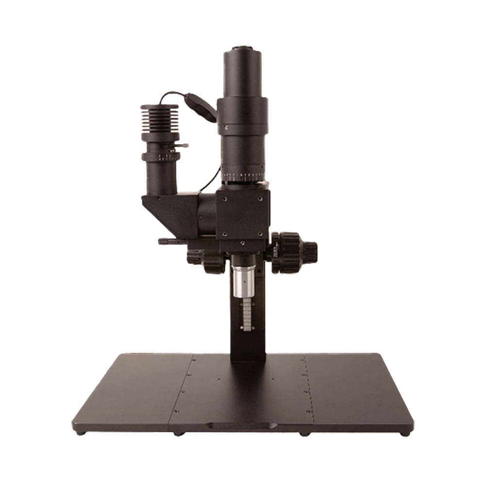
DIC100 Series differential interference contrast microscope system
Product Introduction
The Differential Interference Contrast (DIC) microscope operates on birefringent double-beam polarisation interference:
1. Linearly polarised light from the polariser passes through a birefringent Nomarski prism, splitting into two orthogonally polarised beams with a defined phase difference.
2. When the incoherent beams illuminate the specimen, micro-relief or refractive-index variations introduce an optical path difference; after reflection, the beams recombine upon re-entering the Nomarski prism.
3. The analyser aligns the vibration directions of the recombined beams to produce interference.
4. Interference modulates beam amplitude, enhancing contrast and delivering a pseudo-three-dimensional relief appearance.
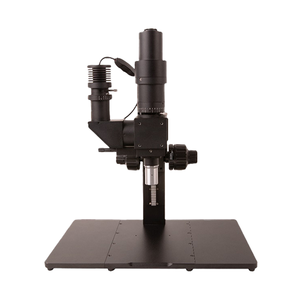
The Nomarski prism can be translated horizontally as a phase compensator, adjusting brightness and interference colours between specimen and background to achieve the desired observation. Figure 1 illustrates the DIC100 differential interference contrast system.
Product Features
- Standard and long working distance objectives available
- Imaging path: 1X (tube lens focal length 180 mm) with optional reducers
- Image circle: 25 mm
- Spectral range: visible light
- Camera interfaces: C / M42 / M52 (optional)
- Illumination: critical illumination or Köhler illumination (optional)
- Light source: 10 W white LED / blue LED (optional)
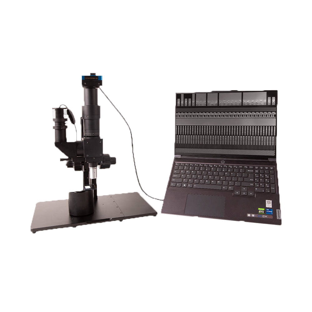
System Configuration and Parameters
Professional differential interference contrast microscopy system providing excellent imaging solutions for transparent samples
System working principle
The Differential Interference Contrast (DIC) system uses birefringent double-beam polarisation interference to achieve high-contrast imaging.
Beam separation
Linearly polarised light passes through the Nomarski prism, splitting into two orthogonally polarised beams with a defined phase difference.
Sample interaction
Two incoherent beams illuminate the specimen; surface relief or refractive-index variations create an optical path difference.
Beam recombination interference
After reflecting from the specimen, the two beams pass through the Nomarski prism again and recombine; the analyser aligns their vibration directions to produce interference.
Enhanced contrast
Interference-induced amplitude changes render sample details with enhanced contrast and a three-dimensional relief appearance.
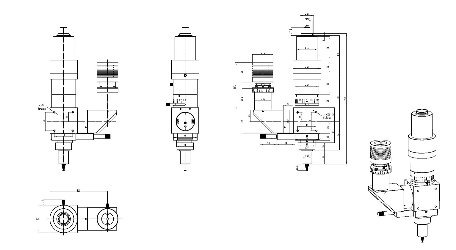
Objective Series Parameters
Standard working-distance objective series (60 mm parfocal distance with a 200 mm tube lens )
| Model | Magnification | NA | Working Distance | Focal Length | Resolution | Object Field | Image Field |
|---|---|---|---|---|---|---|---|
| DIC5XA | 5X | 0.15 | 23.5mm | 39mm | 2.2µm | 5mm | 25 mm |
| DIC10XA | 10X | 0.3 | 22.8mm | 20 mm | 1.1µm | 2.5mm | 25 mm |
| DIC20XA | 20X | 0.4 | 19.2mm | 10 mm | 0.8µm | 1.1mm | 25 mm |
| DIC50XA | 50X | 0.55 | 11mm | 4 mm | 0.6µm | 0.44mm | 25 mm |
Long working-distance objective series (95 mm parfocal distance with a 200 mm tube lens )
| Model | Magnification | NA | Working Distance | Focal Length | Resolution | Object Field | Image Field |
|---|---|---|---|---|---|---|---|
| DICL2XA | 2X | 0.055 | 33.7mm | 100 mm | 6.1µm | 12.5mm | 25 mm |
| DICL5XA | 5X | 0.14 | 33.6mm | 40 mm | 2.2µm | 5mm | 25 mm |
| DICL10XA | 10X | 0.28 | 33.4mm | 20 mm | 1.2µm | 2.5mm | 25 mm |
| DICL20XA | 20X | 0.34 | 29.5mm | 10 mm | 0.8µm | 1.25mm | 25 mm |
| DICL50XA | 50X | 0.5 | 18.9mm | 4 mm | 0.7µm | 0.5mm | 25 mm |
System Technical Specifications
Optical System
- Imaging Path
- 1X (tube lens focal length 180 mm), custom reduction optics available
- Image Size
- 25 mm
- Spectral Range
- 400–700 nm
- Tube Lens Focal
- 200 mm
Illumination System
- Illumination
- Köhler illumination
- Light Source
- 10 W white / 3 W blue LED
Mechanical System
- Camera Interface
- C-mount
- Objective Thread
- M26×0.705
- Prism Adjustment
- Precision lateral adjustment
Typical Application Cases
Successful applications of DIC100 system in various fields
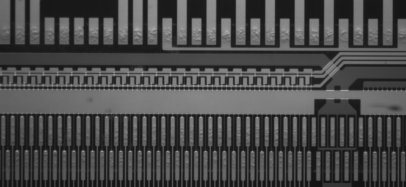
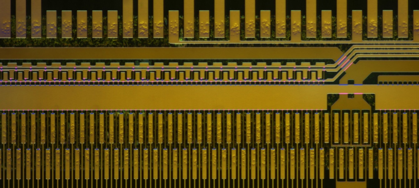
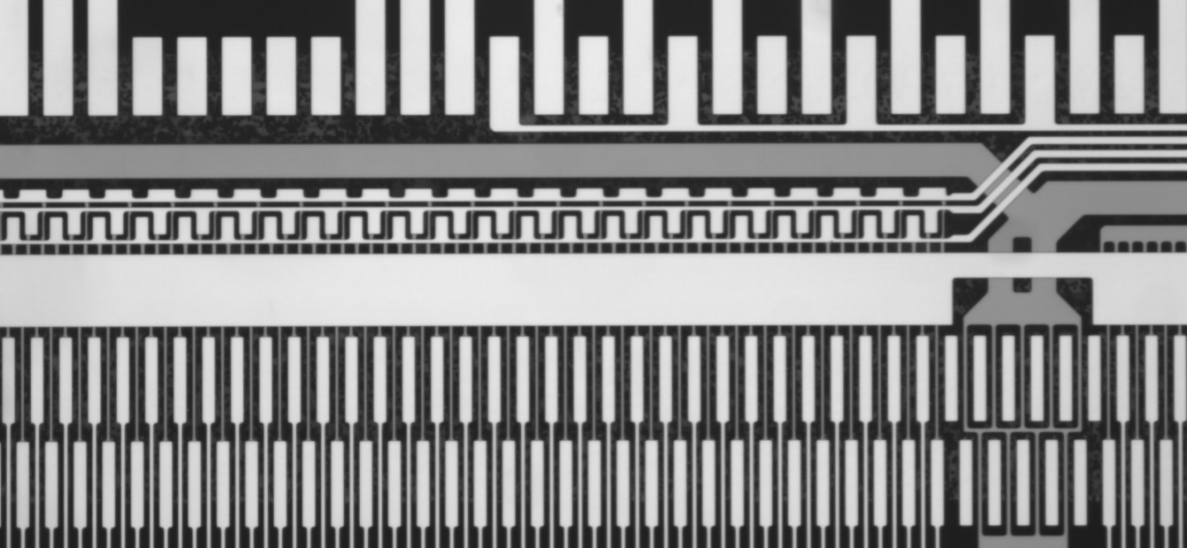
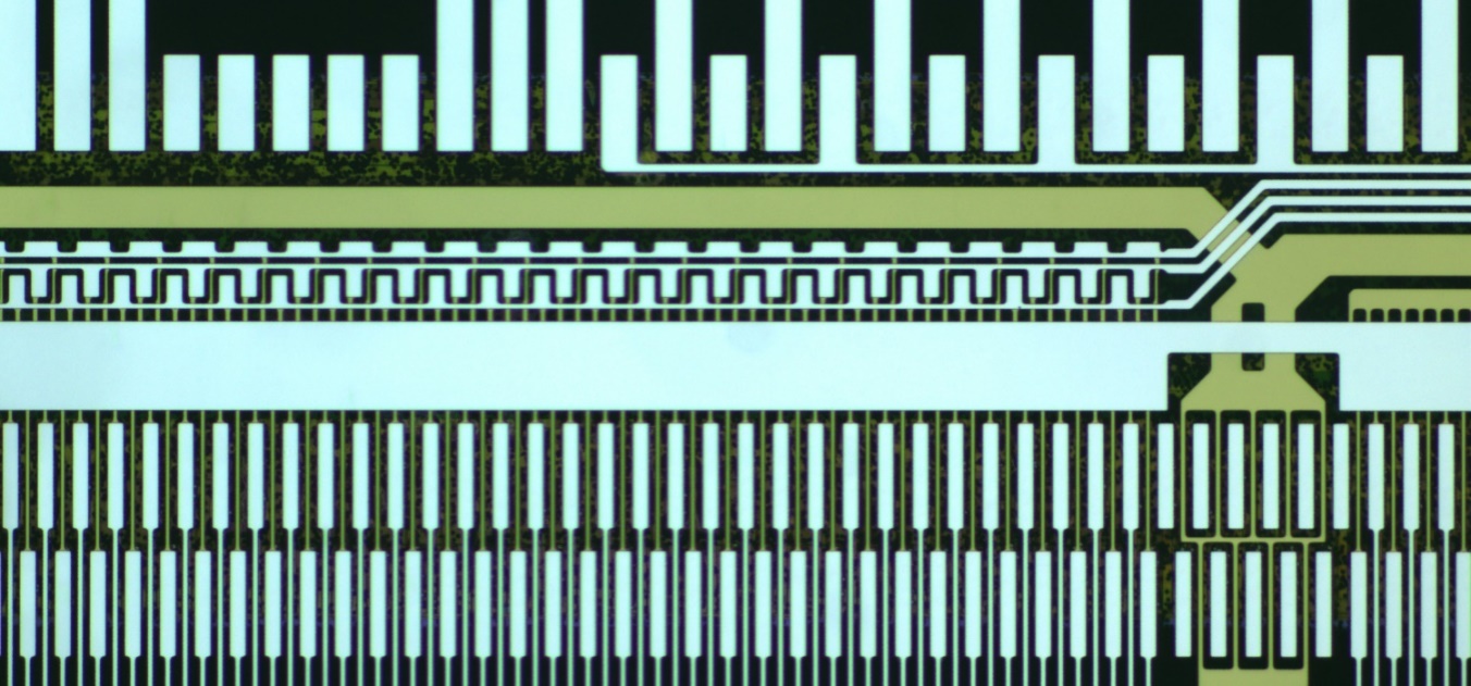
Conductive particle inspection for LCD/OLED products
The number of conductive particles in LCD circuit paths determines conductivity: too few reduce performance and may cause display faults, while too many waste material. The DIC100 system clearly reveals particle outlines, enabling accurate counting and distribution analysis while avoiding errors caused by agglomeration.
- Conductive particle outlines are clearly visible
- Accurately identify and count agglomerated particles
- Improves measurement accuracy
- Blue LED illumination with a monochrome camera yields optimal contrast.
- White LED illumination paired with a colour camera delivers natural colour reproduction.
Detection of surface cracks and defects
As a powerful method for modern metallographic analysis, DIC requires relatively simple specimen preparation and produces pronounced relief under the microscope. It readily reveals fine structures or defects that are invisible or barely visible in brightfield metallographic microscopes.
- Observe particle, pore, crack, and surface relief details within specimens
- Low specimen preparation requirements
- Provides a pronounced three-dimensional relief effect
- Makes materials analysis more reliable
More Application Fields
Microbial cell inspection
The DIC100 series enables non-destructive imaging of live cells. By tuning interference colours according to staining response and adjusting focus, it captures sharp images at multiple depths, revealing internal cell structures with high resolution.
- Non-destructive observation of live cells
- Sharp imaging across multiple focal planes
- Internal cellular contours are clearly visible
Comparison with other microscopy techniques
| Comparison Technology | DIC Technology Advantages |
|---|---|
| Conventional metallographic microscope | DIC reveals fine structures and defects that are invisible or barely visible under brightfield metallographic microscopes. |
| Biological microscope | DIC provides superior contrast and three-dimensional relief, allowing transparent specimens to be observed without staining. |
| Phase-contrast microscope | DIC has no halo artefacts, delivering higher resolution and sharper images. |
| Fluorescence microscopy | DIC requires no staining, enabling live-sample observation while avoiding phototoxicity and photobleaching. |
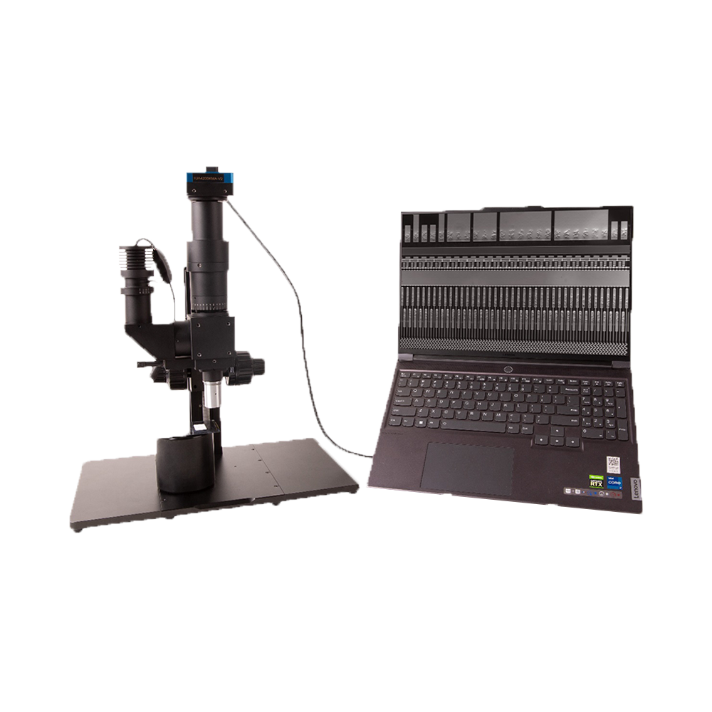
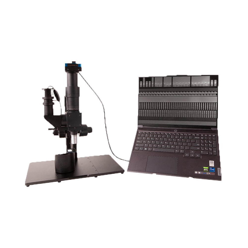
System Configuration and Accessories
Standard Configuration
- DIC100 main system
- Nomarski prism module
- Polariser
- Analyser
- Coaxial polarised illumination module
- Precision focusing stage
Optional Accessories
- Standard and long working distance objective sets
- Rotating specimen stage
- Automated stage control
- Image acquisition and analysis software
- Custom-wavelength LED sources
- Anti-vibration platform
The DIC100 Series features modular design, allowing flexible configuration based on specific application requirements
DIC100 System Advantages
Professional differential interference contrast technology providing excellent imaging effects
Superior Contrast Enhancement
Through dual-beam interference technology, phase differences are converted to amplitude differences, making minute details of transparent samples clearly visible.
Three-Dimensional Imaging
Unique relief effect presents sample surface morphology with three-dimensional appearance, facilitating observation and analysis of minute structures.
Flexible System Configuration
Standard/long working distance objectives optional, adapting to different samples and application requirements, meeting diverse inspection needs.
Precision Adjustment System
Nomarski prism horizontal precision adjustment achieves optimal interference effects and image quality.
Non-Invasive Living Cell Observation
Observe living cells without staining, avoiding phototoxicity and photobleaching, preserving sample viability.
High-Resolution Imaging
No halo effect, resolution superior to phase contrast microscopy, providing clearer image details.